TypK to RGB Led
this little circuit reads a Typ K Thermocouple and indicates the Temperature with an RGB LED.
Read more:
The Quick Specs:
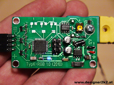
- ATmega168 with only a reset resistor and some noise blocking caps and inductors
- ISP header for programming (to upload the Arduino sketch hex file over avrdude)
- Typ K Thermocouple amplifier with LTC1050 (like here: http://code.google.com/p/multidisplay/wiki/TypKThermocouples)
- MCP9701 for the Ambient measurement directly above the Tyk P connector
- 5V Supply rugged for Automotive use (like here: http://code.google.com/p/multidisplay/wiki/Powersupply)
- 3 Transistors for the R-G-B Channels with Pulldown Resistors

Layout
The Thermocouple is attached to an LT1050 amplifier, and this Signal fed into the ATmega168.
For the Ambient Sensing a MCP9701 is used and directly fed into the ATmega168.
The ATmega168 is getting its 5V out of a rugged 7805 regulator with some protections against the Automotive environment.
3 Transistors then are used to get more switching power to the LED´s what are fed directly from the 12V.
Schematic and Layout: Target Layout
The Code
is written in the Arduino IDE (17 must be used, as the 18 does not generate the hex file, or i dont know where to get it)
Basically it reads the Thermocouple and the Ambient Temperature, adds both and then makes a big if / else if to find what colour would fit 
//d2k2 12.02.2010
//TypK RGB First Test

#include       //for PROGMEN

#define ledPin 9    // STATUS LED connected to PB1

#define PinR  3    //PD3
#define PinG  5    //PD5
#define PinB  6    //PD6

#define TypK  0 //PC0
#define AmbK  1 //PC1

#define Set1  4 //PC4
#define Set2  3 //PC3
#define Set3  2 //PC2


unsigned int Temp;

//Averaging Values:

int TypKraw = 0;
int AmbiRaw = 0;

int TypKcel = 0;
int AmbiCel = 0;
int ResuCel = 0;

int DebugLed = 0;


#define tempTypKReadings 28         //how many entrys are in the Lookup Table
#define MaxTypK 1170                //over that will be seen as Open.

 //Lookup Table for the TypK:
 //from 0-1350�C in steps of 50�C, the list is in �V according to that Temp.
 const unsigned int tempTypK[] PROGMEM =
 {
  0,
  1922,
  3891,
  5831,
  7731,
  9645,
  11599,
  13578,
  15577,
  17590,
  19612,
  21637,
  23660,
  25674,
  27673,
  29652,
  31611,
  33547,
  35460,
  37348,
  39212,
  41050,
  42863,
  44645,
  46396,
  48112,
  49790,
  51431
};


void setup()   {

  TCCR0B = 0x01;   // Timer 0: PWM 5 &  6 @ 16 kHz
  TCCR1B = 0x01;   // Timer 1: PWM 9 & 10 @ 16 kHz
  TCCR2B = 0x01;   // Timer 2: PWM 3 & 11 @ 16 kHz

  // initialize the digital pin as an output:
  pinMode(ledPin, OUTPUT);
  pinMode(PinR, OUTPUT);
  pinMode(PinG, OUTPUT);
  pinMode(PinB, OUTPUT);

  //Make a small LED Test:

  analogWrite(ledPin,5);

   for (int i=0; i <= 255; i++){
      analogWrite(PinR, i);
      delay(20);
   }

  analogWrite(PinR,0);

  for (int i=0; i <= 255; i++){
      analogWrite(PinG, i);
      delay(20);
   }

  analogWrite(PinG,0);

  for (int i=0; i <= 255; i++){
      analogWrite(PinB, i);
      delay(20);
   }

}

void loop()
{

  //Set the Debug Led:
  analogWrite(ledPin,DebugLed);

  //Get the Ambient Value into the Loop:
  AmbiRaw = AmbiRaw * 0.9 + analogRead(AmbK) * 0.1;

  //Get the Thermocouple Value into the Loop
  TypKraw = TypKraw * 0.5 + analogRead(TypK) * 0.5;

  //Convert both into usefull Temps

  Temp = ((5.0*TypKraw)/1024.0)*10000;   //gets the Volts and makes µV out of it (100 is already added from the Amp)
  TypKcel = GetTypKTemp(Temp);                       //Converts the µV into °C

  AmbiCel = ((((5.0*AmbiRaw)/1024.0)*1000)-400)/19.5;    //Makes mV, takes off the 400mV Offset and then divides by the 19.5 coefficient (MCP9701)

  ResuCel = TypKcel + AmbiCel;

  //Get the Light according to the Temp:

  int R = 0;
  int G = 0;
  int B = 0;

  if (ResuCel < 100)
  {
    //Green when the Temp i below 100C
    R = 0;
    G = 255;
    B = 0;
  }
  else if (ResuCel < 200)
  {
    //Yellow
    R = 255;
    G = 100;
    B = 0;
  }
  else if (ResuCel >= 200)
  {
    //Red
    R = 255;
    G = 0;
    B = 0;
  }

  //And set it:
  analogWrite(PinR,R);
  analogWrite(PinG,G);
  analogWrite(PinB,B);

  //wait a little:
  delay(100);

  //Switch the Debug Led from one to the other State
  if(DebugLed == 5)
  {
    DebugLed = 0;
  }
  else
  {
    DebugLed = 5;
  }

}

//This Sub converts the thermocouple µV reading into some usable °C
int GetTypKTemp(unsigned int microVolts)
{
  int LookedupValue;
  //This searches the 2 surrounding values, and then linear interpolates between them.
  for(int i = 0; iif(microVolts >= pgm_read_word(&tempTypK[i]) && microVolts <= pgm_read_word(&tempTypK[i+1]))
   {
    LookedupValue = ((i)*50) + ((50L *(microVolts - pgm_read_word(&tempTypK[i]))) / ((pgm_read_word(&tempTypK[i+1]) - pgm_read_word(&tempTypK[i]))));
    break;
   }
  }
  return LookedupValue;
}
Comments powered by CComment